 Pages Pages
The North American Eagle 2 design concept
A
few months ago I was talking to Barbara Drumheller about ideas to make the
North American eagle an even faster LSR car. The North American Eagle is
a jet powered land speed record automobile. It is owned by Keith Zanghi and
Ed Shadle. It's body is based on a Lockheed F-104 Starfighter fighter
plane originally developed in the early1950s. The Starfighter was nicknamed "The
missile with a man in it" by its pilots because it was very fast and
accelerated quickly.The Starfighter was capable of reaching Mach 2.2 at 30,000
feet altitude and exceeding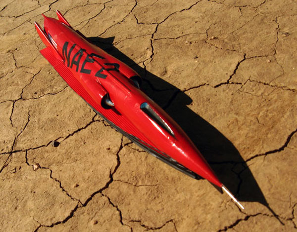 slightly
over1,000 m.p.h. at low altitude. At the time it was deployed it was the
fastest fighter in the world and to this day no single jet engine fighter
has ever been developed that can go faster. It was powered by a four stage
after burning General Electric J-79 jet engine that could develop 17,500
lbs. of thrust. and the engine weighs in the region of 3,800 to 4,000 lbs.
depending on what accessories are bolted to it.
slightly
over1,000 m.p.h. at low altitude. At the time it was deployed it was the
fastest fighter in the world and to this day no single jet engine fighter
has ever been developed that can go faster. It was powered by a four stage
after burning General Electric J-79 jet engine that could develop 17,500
lbs. of thrust. and the engine weighs in the region of 3,800 to 4,000 lbs.
depending on what accessories are bolted to it.
Presently the North American Eagle or NAE is essentially an F-104 with the wings, horizontal tail plane and landing gear removed. Two high speed wheels have been added to struts at the rear and three small wheels have been added under the aircraft near the nose and under the compressor section. The vertical tail has also been cut down slightly. Even though these modifications have reduced the drag on the original aircraft. The wheel drag created by the rolling resistance on a playa will more than equal the overall drag of the original aircraft complete with wings.
A Starfighter can fly or generate lift even without its wings at Mach .89 because of the lift created by its canopy and the nose up attitude supplied by the drag of the vertical tail. These features generate enough lift to pick up the entire aircraft. Presently in order to neutralize this effect the NAE team added canards on either side of the nose. The canards can be tuned to generate negative lift on the nose. The problem with canards is that as they generate negative lift on the nose they pivot the rear of the craft upward around the center of gravity. They also generate additional drag. Canards are a good idea on an aircraft but a bad idea if used on a high speed ground vehicle.
The reasons for this is that they disappear form the airflow as the vehicle yaws and one will have a greater authority in the airflow as the ground bound vehicle yaws. Canards also make all the air in their wake turbulent and this will disrupt body boundary layer air. This increases overall vehicle drag. They also sometimes can add a rolling moment to the vehicle. Lastly in the case of the NAE the canards are located directly in front of the jet engine intakes. This means that the intakes will be in turbulent wake air when they will need to have as laminar an airflow as possible in order to develop full thrust in the engine during a high speed run.
I wanted to come up with a ground effects system that would generate negative lift on the entire NAE without disturbing the clean and efficient aerodynamic lines of the original aircraft designed by Kelly Johnson and the Lockheed Skunk works engineers back in 1951.I also wanted to reduce drag on the original F-104 shape in order to give the vehicle a better shot at achieving 1,000 m.p.h. as its top speed.
I
call the new concept the NAE-2. First in my NAE-2 concept I would remove
the plexiglass canopy blister and replace it with a hatch using a triangular
Gemini capsule type of flush windshield canted back at a 45 degree angle.
This slot window will fill with air and shock at high speed centering a shock
wave over the nose along the center line of the vehicle. It will also give
good forward vision as the driver's face will be very near to it. Canted
back at 45 degrees of angle will also give a less distorted field of vision.
A small oval side window will keep the driver from becoming spatially disoriented
by giving him a side view. I suggest removing the ejection seat and cutting
out the forward firewall and installing a hammock style seat of nylon webbing
woven into a chromemoly rectangular frame. The driver will now be reclined
in a semi supine position and isolated from vibration. Two rings of 2" diameter
thick wall .095 or better 4130 chromemoly steel are bolted at the driver's
head and feet internally to beef up the aluminum shell and the two rings
are tied together with 4130 tube internally. Then the exterior of the entire
cockpit area is wrapped with four layers of S fiberglass in a 360 degree
wrap with the seams 90 degrees apart. This will make the cockpit virtually
indestructible.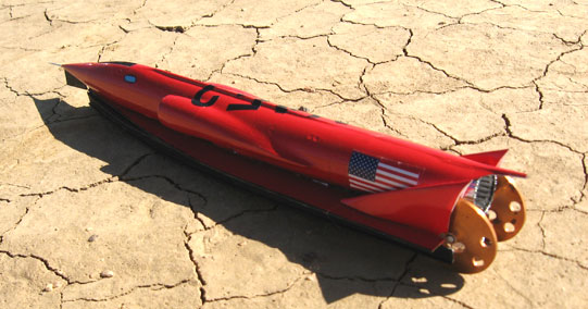
This overall cockpit retro fit will reduce the frontal area of the F-104 by four square feet and make the driver 200 percent safer. An ejection seat is a moderately good idea in an LSR vehicle because of the speed at which accidents happen on the ground. More likely than not if a driver blasted out of a tumbling or exploding LSR vehicle he is probably blasting himself into the ground or along the side of the vehicle. Realistically if he has the time to assess a problem and react to it with a punch out. More than likely this means he also has the time to pull the parachutes, kill the engine and ride it out.
I also suggest removing the rear vertical tail as although it serves an original function in guiding the vehicle's linear path it also imparts a lifting moment on the nose of the vehicle especially in the super sonic regime and that is a bad idea on a ground vehicle.
In its place I offer a supersonic Von Karmon Ogive shaped air dam. Which runs along most of the overall underside length of the vehicle. It consists of a low drag "Laminar flow" or slotted roof section and two curved, shaped composite channels forming the sides of the air dam under the roof section. The channels are hinged at the front where they meet in a razor sharp leading edge. They are linked underneath to a single pneumatic ram which when pressurized spreads them apart at the rear increasing the overall area of the dam and drastically increasing the negative lift load created by the low pressure area within the air dam.
As they spread apart they create a greater low pressure area under the vehicle along its entire length and that will load or add down force or aerodynamic weight to the vehicle without disturbing the overall airflow already established around the vehicle. They are only applied when needed and only opened as much as needed and that is determined by load cells on the wheels. The load cells determine wheel loading and activate the phneumatic ram when there is a positive lifting of weight at the wheels. Air for the ram is supplied from a high pressure bottle on board. The system is totally self sufficient and not controlled by the driver.
The air dam also cleans up the air flow around the wheels on the underside of the car cleaning up the entire car aerodynamically. The dam also reduces high speed airflow to the underside of the body eliminating the F-104's want to generate lift in the first place. The dam also creates a nice area to install the braking parachute tubes.
I have also brought the rear wheels inboard tightly on either side of the jet nozzle. This is to reduce overall aerodynamic drag and frontal area as you don't need a ten foot rear track on a jet car to maintain rollover resistance. The spinning turbine acts as a very good gyroscope.
Jet dragsters have run with tight tracks of wheel width of only three to five feet since the 1950s and I have never heard of one rolling over. A drag strip is much rougher than the Bonneville salt flats or a dirt playa dried lake. So if this was a problem it would have become evident many years ago. Jet dragsters have made tens of thousands of 250 plus m.p.h. runs on hacked up, poorly maintained drag strips all over the world.
Historically an active load changing device was first used successfully by Art Arfons on the Green Monster jet car first built in 1964. The system consisted of a large rectangular neutrally symmetrical 5 foot by 3 foot wing over the front axle of the car. The wing was mounted on struts above the car and was activated by a hydraulic cylinder which was linked directly to a slave cylinder on the front suspension. The idea was that if the front end got light the slave cylinder would pump fluid into the wing cylinder changing the angle of attack of the wing, bringing the rear of the wing upwards and developing a negative lift moment on the front axle. This worked well even though there was no real data to show it. Then in 1966 during a record attempt a front wheel bearing froze up and the right front wheel came off. The front right corner slammed into the salt surface and pitched the car end over end. The large wing or canard was of no use during the crash and may have even helped pitch the car over.
Later the Thrust SSC team in 1997 employed a pneumatic cylinder which jacked up the rear of the car or lowered it as needed. A "T" tail was mounted at the rear of the car to load the car drastically by changing the angle of attack of the entire car. The angle of the car changed as the cylinder was pressurized. This is a marginal idea because in changing the overall attitude of the vehicle in the transonic regime the flow around the vehicle will totally change and could result in lifting or a roll moment anyway. Luckily that never happened but the Thrust SSC was notorious for snapping right and left in the transonic regime as film and the driver will attest.
On NAE-2 I also suggest using much greater diameter wheels at the rear than at the front of the NAE 2 design. The larger wheels at the rear will rotate at a slower RPM than the smaller front wheels and give the front wheels a greater authority in directional stability. The large rear wheels can be covered with fairings or spats that will act as vertical tail fins. The difference is that the vehicle will feel the drag of these fins underneath the vehicle instead of on top. So they will generate more negative lift on the vehicle as opposed to pulling the nose up. Inboard shock created by the fairings will be neutralized by the thrust of the engine but the outboard shock will aid in directional stability.
I also added a steerable fin under the chin of the nose of the NAE-2 to aid in steering. This is because throttling a big jet like a J-79 induces a great torquing moment that can over power the authority of the steering wheels. The steering fin is an insurance policy for directional control. It also helps minimize the leading edge shock on the air dam that could disrupt the flow from moving around the dam. These improvements will yield a top speed in excess of 1,000 m.p.h for the NAE-2 design. These ideas are my gift to the hard working and determined crew of the North American Eagle.....Waldo