Sonic Wind & Constitution LSRV
Concept Pages

The Low Transonic Pylon Air Racer
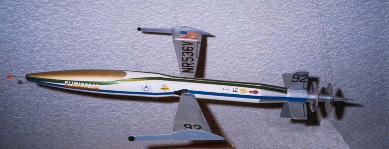
The beauty of piston powered, propeller driven air racing is still played out every fall at Stead field in Reno Nevada. Last season a couple of the favorite unlimited class, highly modified world war 2 fighter planes were lapping the course at greater than 500 miles per hour. These unlimited air racers are pushed to their limits and this is evident by the slow increase in their speeds over the years. During world war 2 stock propeller warbirds could hit speeds of slightly over 400 miles per hour. Nearly 60 years later the highly modified warbird air racer is going 100 miles per hour faster. The radial and inline engines of these planes are pushed to destruction to accomplish these speeds. These planes and their engines are virtually priceless to history and the number of them are dwindling away each year. I offer a new type of air racer. A cheaper, lighter, smaller and faster racer. A racer that would run in the 600 plus mile per hour range with an eye on low altitude stability in the low transonic speed regime. This racer would have a seamless, composite step down tapering body which would constantly accelerate the airflow encountered by the aircraft. An aero spike sphere on the nose would begin to move the air molecules out of the planes way before the plane got there reducing drag. Powered by a 1,200 horse power T-58 gas turbine engine turning two or three small diameter props pushing the aircraft rather than pulling it. The props would be geared to counter rotate from the spin of the turbine impellers. The props would be rigidly mounted to a spinning rear aero cone whose total mass would exactly equal the mass of the impellers in the engine. There would be no torqueing when the engine was throttled up or down. The cruciform tail and the prop drag would offer fantastic directional stability. The bottom tail section would house a spring steel skid for landing as this is a tail dragger. The two landing wheels are mounted on booms extending forward of the wing endplates lowering drag and offering a wide stable wheel track similar to a Focke Wulf 190. For landing the endplates turn down together lowering the main gear. They are linked to a common electrically driven shaft running through the center tubular spar of the wing. The wing is built of various thin wall 4130 chrome moly tubing running through the fuselage and welded side by side and bent so that a butterfly of two long, narrow triangles are formed. The moly tube is spread out to a narrow fan shape on either side of the fuselage and covered with a paper thin moly sheet welded to the tube structure.
This monocoque wing will be thin, strong and flexible. Thin wall moly tubing has memory and durability. At the end of each wing a large airfoil will be employed for extra lift and stability moment. This could be composite foam coated with aluminum sheet epoxied on to the thin wing section. Air on either side of the fuselage and at the wing root would be ducted into the engine through two large NACA ducts and cleaned up by the airfoil shape of the wing tubes in the fuselage.This air is used in the turbine and the resultant expelled gasses are blown back through a tail pipe into the propellers to increase the thrust of the propellers. The propellers being of small diameter and made of titanium would be boosted by these gasses. There would be no need for shock absorbers on the landing gear as the wing tubing bent up slightly to offer dihedral for flight stability would make the wing into a spring to dampen landing shock on the wheels. Fuel would be carried behind the pilot so as the aircraft progressed in race time
the Cg would shift backward at the end of the race rather than at the start. Pilot would lie in a high G supine position for good G recovery and look through a large bubble for good visibility like a glider. 1,200 lbs. 1,200 horse power, .2 Cd and less than 12 square feet of total area. Well you do the math.....Waldo